A Better Look at Things Continued
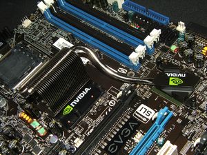
The main thing you notice when you look at this motherboard is the chipset cooling setup, it sort of sticks out with it’s bright green Nvidia logo and shiny heatpipe snaking it’s way across the board connecting the north and south bridges.
The northbridge chipset cooler is big in both height and width and only gets bigger once you add the included cooling fan.
The cooling fan is semi-easy to install, the included screws are tiny, and I dropped them a couple times before I finally got them installed. Technically you shouldn’t be using a magnetic screwdriver with your motherboard but short of holding it upside down over your head and balancing the tiny screw on the tip of your screwdriver, you aren’t going to have fun installing the cooling fan. So, I guess you figured out that I ended up using a magnetic screwdriver to hold the screws while I attached the cooling fan…
The southbridge heatsink in nowhere near as impressive as the northbridge but it does add some color and I’m guessing it should work just fine. I did pull the heatsinks off to inspect ‘under the hood’ and I found gobs of thermal compound, it looks like someone took an entire tube and squeezed it on there… yuck…
The CPU area seems fairly clear of any obstructions and I was fairly sure I could install any CPU cooler and everything would be great, but I was wrong… I tried to install my Coolink Silentator CPU Cooler and guess what got in the way?! The northbridge chipset cooler! You’ll also notice on the top and left sides of the CPU socket are two other heatsinks, the one of the left is an interesting wavy pattern, while the top one is short and rather unassuming, above the wavy heatsink is the 8-pin power connector as well, it’s sort of jammed in there leaving little room for fingers… After seeing the looks of the thermal compound mess under the other heatsinks I thought it might be a good idea to check under these two smaller ones as well, and it’s a good thing I did as they were not even touching half of the chips they were supposed to be keeping cool, how that works I’m not quite sure… Last I checked you needed some sort of contact with the chip you were trying to cool to transfer the heat away from it to the heatsink… There was some sort of thermal film attached to the bottom of the heatsinks, but it was this very thin layer, the exact opposite of what I saw under the other chips… So I cleaned them up and applied some Arctic Cooling MX-2 non-conductive thermal compound and made sure they are seated correctly and all is well now…
In the bottom right corner of the board, around the southbridge is where you’ll find quite a few connectors, including an LCD type of display for BIOS messages. Next to the display are two more USB headers bringing the total to ten USB ports for this board, more than enough for anyone and any extra devices you might have. I mentioned earlier there are a total of six SATA connections, four are mounted normally while a set of two are mounted on the side of the board, for what reason I’m not to sure… In this are you’ll also find four three pin fan headers, clear CMOS jumper, serial port connection, and a side mounted floppy connection.
On the top right side of the EVGA nf680i mobo you’ll find the four DDR2 ram slots, next to those towards the edge of the board is the SATA connections, above those we find the front panel header and standard molex connection for extra power to the board. On the edge of the mobo is the IDE and main power connections as well. I found the placement for the front panel header to be very odd and a bit difficult to get at especially is the ram is installed and the power connection, at first I couldn’t even find this header on the board, it took a minute or so to figure out where it was, I thought the serial header at the bottom of the mobo was the front panel header…
Moving to the left side of the board, starting at the bottom we’ve got even more headers, including front panel audio, spdif, firewire (located between the slots) and power and reset buttons as well.
Moving up we have the PCI and PCIE slots, the PCIE slots are colored, one is blue and two are black, the black colored ones are for an SLI setup to use the rather long SLI bridge we saw earlier…
Well that’s it for the tour part of this review, so let’s move on…


